Overview
The Linaro Automation Appliance (LAA) is a critical component within [Linaro Remote Labs](https://linaro-onelab-user-guide.readthedocs-hosted.com/en/latest/remotelabs_overview.html).
In summary, the LAA is a carrier platform designed to host DUTs for remote testing using the Linaro Automated Validation Architecture (LAVA), an open-source Test Automation Framework (TAF). LAVA enables automated testing of low-level hardware interactions, firmware validation, driver testing, and application-level payloads to ensure stability, compatibility, and compliance with hardware requirements. At its core, the LAA functions as a fully integrated Embedded Device Testing Harness, seamlessly connecting a DUT to the test environment. This innovative approach represents a significant advancement in embedded platform validation, offering multiple benefits for automated testing and compliance assurance.
As a fully integrated Embedded Device Testing Harness, the LAA seamlessly connects a DUT to the test environment, enabling efficient and automated validation. This approach enhances embedded platform testing by improving reliability, streamlining workflows, and ensuring compliance with hardware and software requirements.
Benefits include:
A uniform form factor that provides mechanical security to attached test devices
Eliminates the need for external cables, USB hubs, secondary relays, serial concentrators, DC power bricks when using POE, and programmable PDUs
A unique design that provides the ability to attach to a very basic Mechanical Interface Board(MIB). The MIBs provide custom control components, eliminate extraneous and unreliable wiring, and greatly increase long-term reliability of embedded lab CIs.
Integration of Automation control software which further eliminates the need for additional lab equipment.
I/O pinoouts can be aligned to do same functions on different platforms simplifying the automation integration
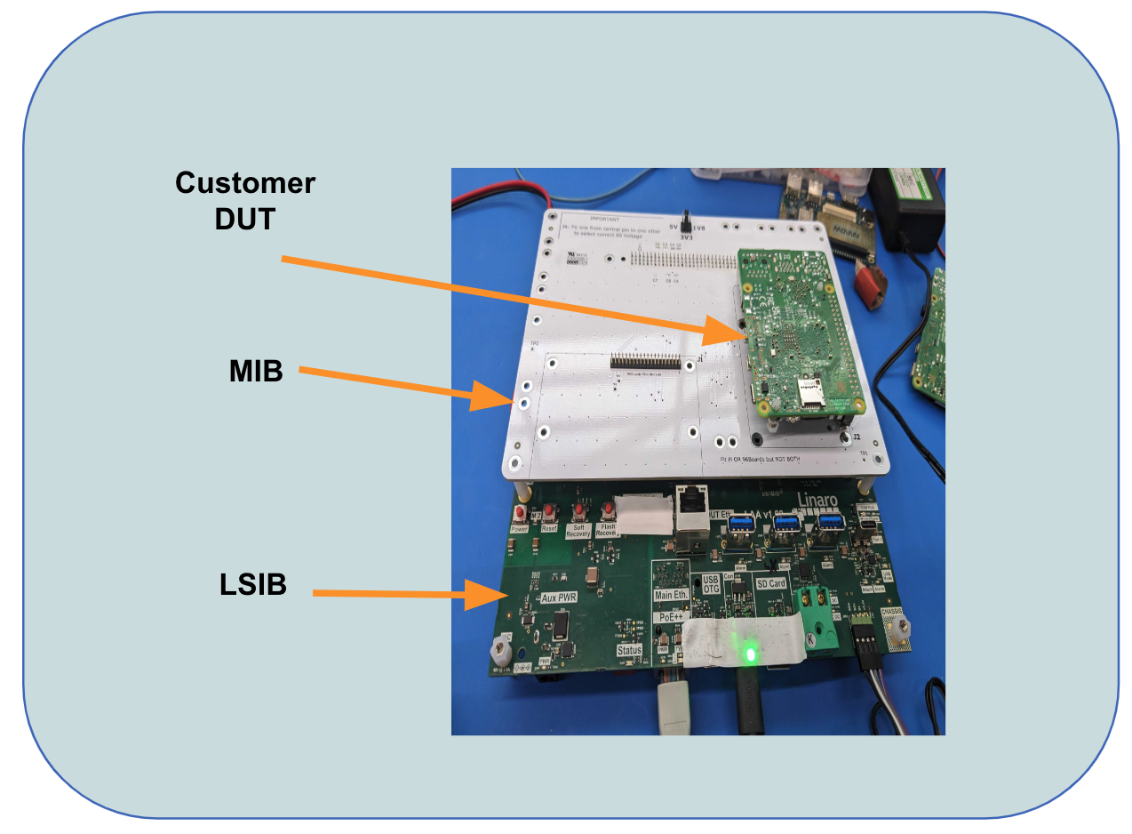
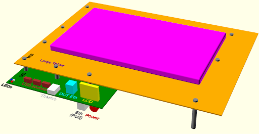
The above figure shows the primary components of the LAVA Automation Appliance. The platform is composed primarily of 3 separate hardware components as shown in the figure shown in the Overview section.
Linaro Standard Interface Board (LSIB)
The LSIB is the compute engine of the LAA, facilitating communication with the cloud-based Managed LAVA Server and Fleet Management modules via HTTPS and the LMS API. It controls the DUT, manages device registration, handles user authentication, enables OTA updates, and performs various other critical functions.
The LSIB provides a standard interface connector to allow for the connection of various MIBs as described in the Mechanical Interface Board (MIB) section.
A summary of the features available on the LSIB include:
Status Indicators (OLED Panel / LED’s)
OLED: MacID, IP Address, Identifier Beacon, Customizable
LEDs: Pwr, USB, Eth, DUT, NVME status, other
Two Ethernet ports (RJ45)
One for DUT connection, the second for Cloud Connection to the LAVA Managed Server
Three USB-C 2.0 ports
OTG storage drive emulation
Serial access
ADB (Android DeBugger) support
Power delivery
A 4 Port USB 3.0 Hub - individually switchable
A Thermocouple for measuring DUT temperature
Onboard NVME for shared Host/DUT storage
Standardized 96-pin Connector to support customizable MIB’s - Multi-use Expansion GPIO Pins (I2C, Uart/Console, SPIO)
Single source Host and DUT power through POE+
Power distribution using Solid State regulator banks
Selectable Voltage support (12v, 5v, 3v3, 1v8)
Individually Switched programmable Power Rails
Associated S/W Repositories
There are several s/w repos available that are related to the software running on the LSIB to include the following:
LAVA Dispatcher: add here
Other?: add here
TODO: MAY OR MAY NOT BE PUBLIC - COULD INCLUDE EVEN IF PRIVATE?
Mechanical Interface Board (MIB)
The MIB is a separate board that provides basic PCB mapping between the LSIB and the DUT. This helps to solve the problem that no two embedded platforms are alike, and hand wiring has been found to be unreliable, historically causing many hardware faults in labs post-installation due to rack vibrations, slight board movements, etc. The stability provided in a setup using mechanical connectors such as on MIBs greatly improves lab installation long-term reliability and sustainability.
MIBs can also be customized to include active circuitry for use cases requiring voltage stepping, external regulators for automation control, and LSIB expansion GPIO for component control.
The follow section provides more details on existing MIBs.
MIB Variants
MIBs can come in multiple variants to support standard interfaces. This section will provide several of the ones currently developed by Linaro and provide a brief description.
96Boards / Raspberry Pi
The images below show platforms using the 96Boards/RPi MIB variant.

DragonBoard410c on 96Board MIB
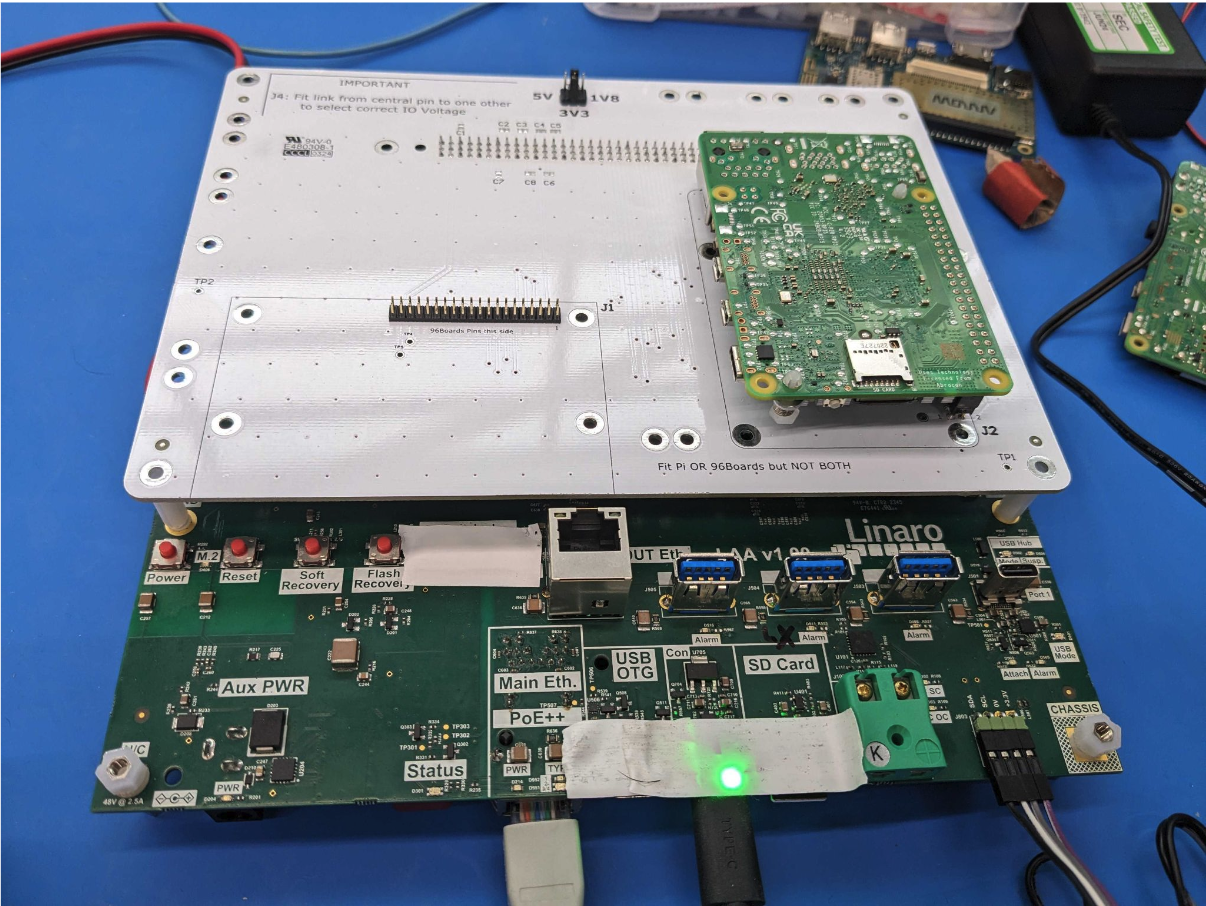
RPi on 96Board/RPi MIB
The above two figures leverage the same MIB. This MIB supports both a 96Board connector layout and a Raspberry Pi standard connector layout on the same MIB.
Warning
Make sure that the jumper configuration is placed in the correct voltage setting for platform that has been plugged in (5v, 1v8, or 3v3).
TODO: more jumper config details, power cable connections, Ethernet, USB to get to console, power cycling
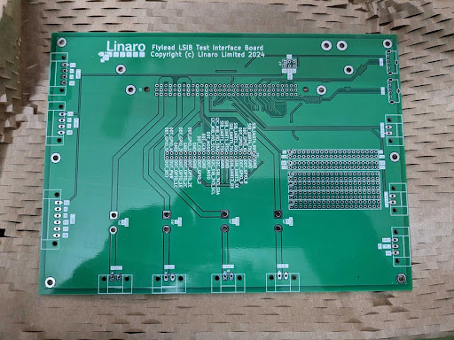
Flylead Variant
Another available variant is called the Flylead MIB. This is a generic variant supporting the ability to custom wire a solution. This variance can control carrier boards or devices with enclosures with a MIB hosting screw-terminal fly-lead headers. If may be a good starting point to prototype a solution prior to committing to a Custom Variant being built.
Wireframe MIB
For small deployments, this MIB is the most likely candidate to leverage. If a platform is going to be leveraged in a larger scale across multiple remote locations in multiple CI instances, the next section may be more applicable.
Custom Variants
Even with Linaro developing variants for well-known platforms, there still remains the challenge that embedded platforms come in endless configurations when it comes to connector layouts/types, reset circuitry, and voltage controls. Thus the problem of dealing with this variation isn’t solved single handedly with a single MIB. This has led to the development of standard MIB circuit platforms for specific embedded boards.
The LAA modular architecture allows for a very basic and economical custom MIB to be created that, once created, can be built very cheap and bring greater reliability to lab solution setups. These MIBs can also be made available to customers to ease in their usage of platforms in CI environments. One example of this is below.
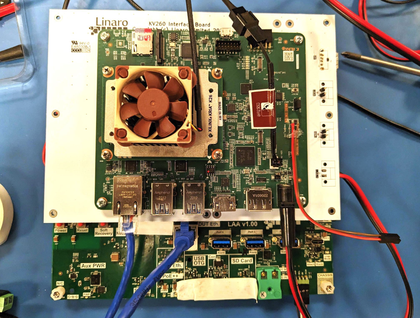
AMD KV260 on custom MIB
The above MIB has been custom designed for the AMD KV260. Linaro will work with Remote Lab customers in the creation of such custom solutions, if needed, as part of the Assessment Review <https://linaro-onelab-user-guide.readthedocs-hosted.com/en/latest/onelab_platform_enablement.html#onelab-comprehensive-assessment-review> section of the ONELab Users Guide.
Oversized MIBs
It’s also possible that some development platforms are larger than the LSIB and placing them on a standard size MIB may not be a wise approach. For those cases, it can be kept in mind that a MIB can actually extend beyond the size of the standard LSIB. It can use standoffs to assure the MIB provides the mechanical stability needed. At this point there are no such MIBs, but when the time comes, the creation of such a MIB will be possible.
Oversized MIB example
Device Under Test (DUT)
This is the customer board that mounts to the MIB. When mounted, it attains power and interface connectivity from the MIB to the maximum extent possible.
Note
In some cases, DUT Platform power may be drawn through ethernet or USB cables and not the MIB.
Introduction to Automated Device Testing
There are several generic features required by all embedded platforms that are targeted for Linaro Remote Labs, and Validation & CI Labs in general. This section provides a brief overview of the minimum set of features, and supporting information, needed and why they’re needed.
Minimum Featureset for Automated Device Testing
One of the challenges in instrumenting embedded platforms for validation and test labs is the fact that each platform often has a slightly different configuration when it comes to functionality. To efficiently integrate platforms into a Linaro Remote Lab infrastructure, this section summarizes the features needed as well as the information required by Linaro to integrate the platforms into a lab.
Console Connectivity and Access
Connecting a console from the LAA to the DUT is the first essential feature. Not only is this used for initial bring up and enablement, but it’s also used to capture outputs during testing to validate DUT functionality and test status (pass/fail). In embedded systems, platform providers choose various methods to connect consoles including over USB, Serial UART, and Network Connections. It’s also important to understand the communications protocols being used such as Telnet, SSH, or other. For UART setting up parameters such as baud rate are essential for a successful connection. It’s also helpful to understand the software tools an organization uses such as PuTTY,minicom, and SSH. This information must be made available and can impact both the hardware interfaces and software solutions and configurations needed to communicate at this fundamental level with the DUT.
Firmware Update and Recovery
The next feature that must be well understood when deploying embedded systems into a validation and test CI infrastructure is the processes, procedures and tooling needed to update firmware or restore/recover a DUT in which the firmware has been corrupted causing the DUT to no longer boot (i.e. recovering a “bricked” platform).
Memory type/capacity such as ROM, RAM, EEPROM, and the layout of the memory are important in helping to understand how the firmware is stored and executed. The bootloader technology deployed (U-Boot, GRUB, UEFI) is important as well, and in some instances is even required for compliance purposes (for example UEFI for SystemReady). Any details in regards to recovery and fallback are helpful to understand as well.
Power and Reset Considerations
It’s important to understand several factors regarding provision of power to the DUT as well as how this may impact platform reset functionality. These factors include the input voltage range/tolerance, power source (via power barrel connector vs a header pin for example), and thermal considerations. Some platforms, for example, can accept power from multiple sources such as POE(Power Over Ethernet), through a USB connector, through a dedicated power barrel connector, or in some cases from more than one of these. Knowing this is important to automation. For example, if a setup assumes a DUT can be reset by cycling the power to a dedicated power barrel connector, but the platform remains powered through POE, then the reset won’t occur. In other cases, a dedicated button on the DUT may be expected to be depressed to reset the platform and the platform may require modification to perform this through automation. Any thermal requirements such as heat sinks or airflow over certain devices can impact the installation solutions as well. These details need to be provided during the solution assessment phase and can impact the MIB solution for a DUT into a Linaro Remote Lab. The LAA can provide various input voltage levels such as 3v3 or 1v8 to a DUT through an MIB connector, for example, but based on the results of this section, may or may not be required. A DUT may ideally have the ability to be reset through header pins as well, but this isn’t always the case.
Network Connectivity
Understanding and providing information on how the DUT connects to an Ethernet network is important. Is there a physical RJ45 connector? What are the details on initial connectivity? Are SSH connections needed/used? (See the Console Connectivity and Access section) Is the network boot a supported configuration? All these details are helpful in understanding during the initial setup phases to deploy an optimal solution.
OS Installation
Providing details regarding the OS to be used are also important. Will this need to be downloaded upon each boot cycle? Is there a default OS image locally installed on the DUT? Can this process currently be performed without human intervention or are there steps required by a user? Any other details and nuances regarding the installation of the OS are helpful in setting up the automated test environment.
Documentation and Tooling
For all the above features in this section, the platform provider should be prepared to provide any and all documentation pertaining to the above including but not limited to schematics, board layout, bootloader installation procedures, recovery procedures, known issues, logging configuration, custom tooling/scripts, version compatibility, and firmware installation procedures.